Hypergate
Overview The 5 MW Lane 01Generator 02Power 03Space Cooling 04White Space 05Air-Cooled Chiller Plant How We Build Delivered Team Careers Contact

The 5 MW Lane

Five factory-built blocks make 5 MW. It is the unit Hypergate delivers and the only thing a campus repeats.

Patent Pending

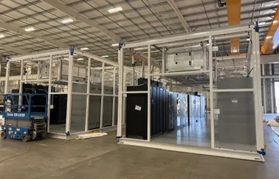
Generator MCG Standby generation. Enclosure, fuel system, and controls set and wired in the plant. Power MCG UPS, distribution, fire suppression, and cooling in one block, tested as a unit on skids. Space Cooling SVL High-density, liquid-ready mechanical cooling matched to AI rack densities. White Space Century Mission Critical The data hall, delivered White Space Ready for tenant fit-out. Air-Cooled Chiller Plant SVL Heat rejection outside the lane, down the long side, piped and tested in the plant.

Lane Specification

Lane capacity 5 MW
Blocks Five, factory-built
Commissioning L1–L3 in the factory, on skids · L3–L5 on site
Efficiency Top-20% HPC annualized PUE
Utility service Dual high-voltage feeds in 2N · 100–345 kV
Site labor 62–70% less electrical · 45–54% less mechanical

Figures per the Hypergate technical data package.

L1 is factory acceptance and L5 the integrated systems test at full load. The full sequence is on How We Build.

The lane-based architecture is patent pending.

Inside the Lane

Walk a lane front to back and you cross seven bands, from the transformer yard to the chiller yard. Hover a block on the render to see who builds it. Click to open its page.Tap a block on the render to open its page.

5 MW LANE
Plan view of one 5 MW Hypergate lane: generator, power, space cooling and white space in a row on a common slab, with the air-cooled chiller plant outside the lane at the end

Hover a block on the lane. Click to open its build page

Front of the lane Back of the lane

The Equipment

The machines that fill a lane.

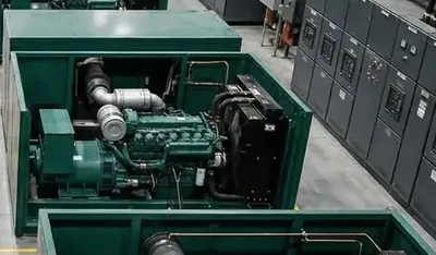
Generator
Generator 2 per lane

Engine and alternator on a skid, set in a row down the generator room.

Power skid
Power skid 2 per lane

Arrives as one piece, electrical cabinets already built in.

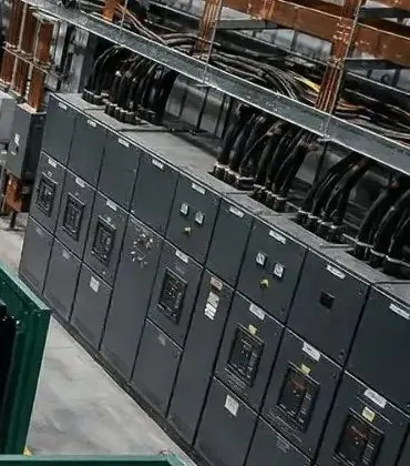
Switchboard lineup
Switchboard lineup 2 per lane

Cabinets bolted into one long row, working space kept in front.

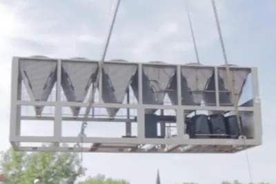
Air-cooled chiller module on the crane hook
Air-cooled chiller 4 per lane

Fans across the top, coil banks down both flanks, set by crane in one piece.

Stacks and louvers
Stacks and louvers Generator room

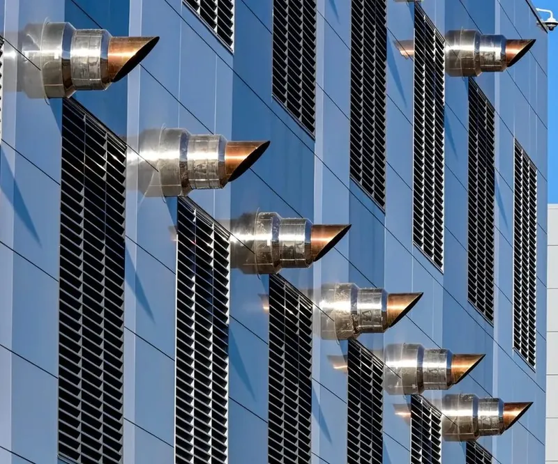
Exhaust stacks on a regular rhythm along the long elevation.

Cooling and Density

Space cooling is sized to AI rack densities and built liquid-ready for loads that move. Heat rejection runs down the long side of the building, outside the lane, and cooling capacity arrives with the lane it serves.

Densities 60 kW to 750 kW racks
Air side Fan-coil walls carry 40% of lane load
Liquid Secondary loop serves 60%+ of rack load
Fit-outs Immersion-to-water, containment, underfloor, distributed air
Economizing Free cooling from 39°F at full load
Heat rejection Air-cooled chiller plant, outside the lane
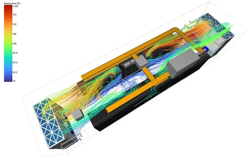
CFD render of airflow through a data hall
Airflow through the white space

Reliability

Every lane carries its own redundancy, and the campus holds spare lanes on top.

Lane capacity N+2 Spare lanes at the campus. Any lane can come out of service without touching tenant load.
Maintainability Tier III intent Power and cooling paths stay concurrently maintainable.
Failure modes Full lane backup Independent mechanical and electrical paths. No single point of failure.
Monitoring and Controls Every lane reports into one owner-run control plane, watched the same way across the campus.
Platform Centralized SCADA with local PLC control of plant systems.
Gateways Redundant BMS, CMS, and EPMS integration.
Historian Two years of retention for trending and analytics.
Protection Integrated alarming, failover, and leak detection in the white space.

Scaling to a Campus

Lanes sit side by side in rows on a shared site backbone. Every lane added is another 5 MW.

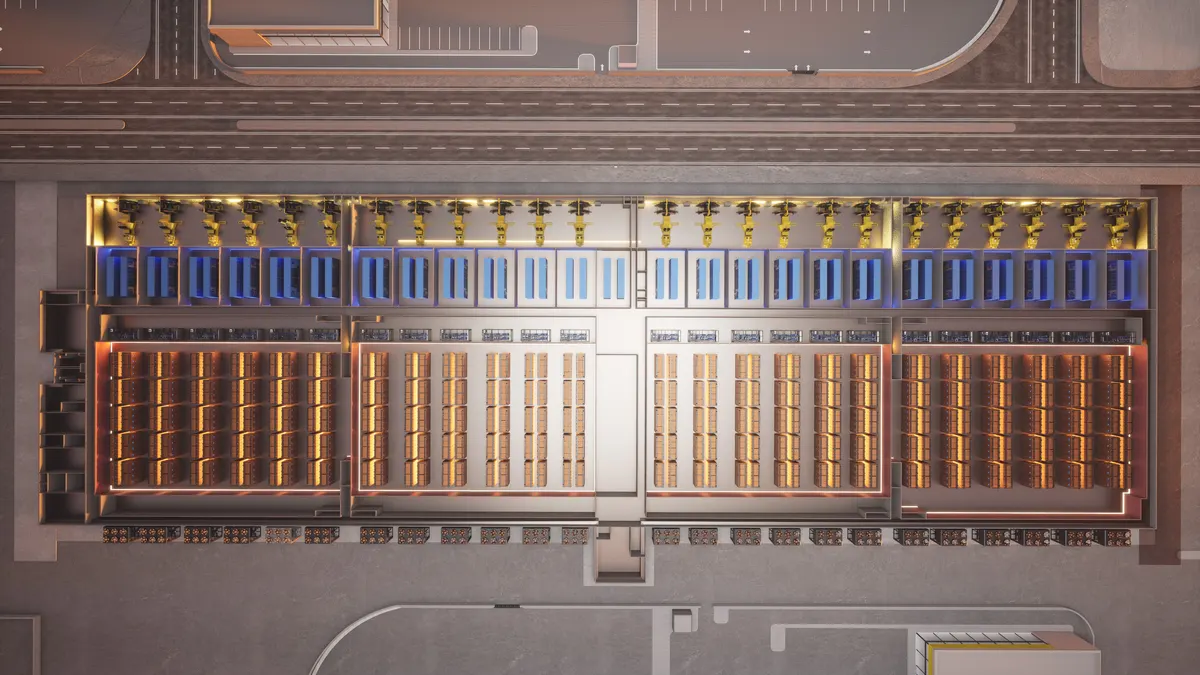
Top-down render of the whole building with the roof off: generators, power, cooling, and white space repeating lane after lane, with the chiller yard outside along the long side
One lane's systems, repeated across the hall. Generation, power, cooling, white space
5 MW 1 lane
20 MW 4 lanes
50 MW 10 lanes

The 100 MW Reference Design

Campuses start from a published reference design, sized at 100 MW and grown in phases.

Baseline 100 MW IT 94 MW compute plus 6 MW network and control.
Site capacity 138 MW Connected load. PUE 1.20 annualized, 1.38 peak.
Growth 400 MW IT Eight phases, up to 552 MW connected.
Posture NTP-ready Integrates customer site requirements.

Reference design figures per the Hypergate technical data package.

Contact

Tell us the capacity you need and the date you need it running.

Contact Hypergate